
NCERT Solutions for Class 10 Science Chapter 12 Electricity
NCERT Solutions For Class 10 Science Chapter 12 Electricity: In this article, we will provide you all the necessary information regarding NCERT solutions for class 10 science physics chapter 12 electricity. Working on CBSE class 10 physics electricity questions and answers will help candidates to score good marks in-class tests as well as in the CBSE Class 10 board exam.
Electricity class 10 NCERT solutions will not only help in board exam preparation but also helps in clearing the competitive exams like Engineering. Also, candidates can find electricity class 10 numericals with solutions which helps candidates solving their assignments. Read on to find out everything NCERT Solutions For Class 10 Science Chapter 12 Electricity.

NCERT Solutions for Class 10 Science Chapter 12 Electricity
Before getting into the details of NCERT Solutions For Class 10 Science Chapter 12 Electricity, let’s have an overview of the list of topics and subtopics under Electricity class 10 NCERT solutions:
- Electricity
- Electric Current And Circuit
- Electric Potential And Potential Difference
- Circuit Diagram
- Ohm’S Law
- Factors On Which The Resistance Of A Conductor Depends
- Resistance Of A System Of Resistors
- Heating Effect Of Electric Current
- Electric Power
Free download NCERT Solutions for Class 10 Science Chapter 12 Electricity PDF in Hindi Medium as well as in English Medium for CBSE, Uttarakhand, Bihar, MP Board, Gujarat Board, and UP Board students, who are using NCERT Books based on updated CBSE
In Text Questions
Page No: 200
1. What does an electric circuit mean?
Ans:A continuous and closed path along which an electric current flows is called an electric circuit.An electric circuit consists of electric devices, source of electricity and wires that are connected with the help of a switch.
2. Define the unit of current.
The unit of electric current is ampere (A). 1 A is defined as the flow of 1 C of charge through a wire in 1 s. A = I C s-1
3. Calculate the number of electrons constituting one coulomb of charge.
Ans:One electron possesses a charge of 1.6 ×10⁻¹⁹C, i.e., 1.6 ×10⁻¹⁹C of charge is contained in 1 electron.
Page No: 202
1. Name a device that helps to maintain a potential difference across a conductor.
Ans:Any source of electricity like battery, cell, power supply, etc. helps to maintain a potential difference across a conductor.
2. What is meant by saying that the potential difference between two points is 1 V?
Ans:If 1 J of work is required to move a charge of amount 1 C from one point to another, then it is said that the potential difference between the two points is 1 V.
3. How much energy is given to each coulomb of charge passing through a 6 V battery?
Ans:The energy given to each coulomb of charge is equal to the amount of work which is done in moving it.
Now we know that,Potential difference = Work Done/Charge
∴ Work done = Potential difference × charge
Where, Charge = 1 C and Potential difference = 6 V
∴ Work done = 6×1
= 6 Joule.
Page No: 209
1. On what factors does the resistance of a conductor depend?
The resistance of a conductor depends upon the following factors:
→ Length of the conductor
→ Cross-sectional area of the conductor
→ Material of the conductor
→ Temperature of the conductor
2. Will current flow more easily through a thick wire or a thin wire of the same material, when connected to the same source? Why?
The current will flow more easily through a thick wire than a thin wire of the same material. Larger the area of cross-section of a conductor, more is the ease with which the electrons can move through the conductor. Therefore, smaller is the resistance of the conductor.
3. Let the resistance of an electrical component remains constant while the potential difference across the two ends of the component decreases to half of its former value. What change will occur in the current through it?
According to Ohm’s law
V = IR
⇒ I=V/R ... (1)
Now Potential difference is decreased to half
∴ New potential difference Vʹ=V/2
Resistance remains constant
So the new current Iʹ = Vʹ/R
= (V/2)/R
= (1/2) (V/R)
= (1/2) I = I/2
Therefore, the amount of current flowing through the electrical component is reduced by half.
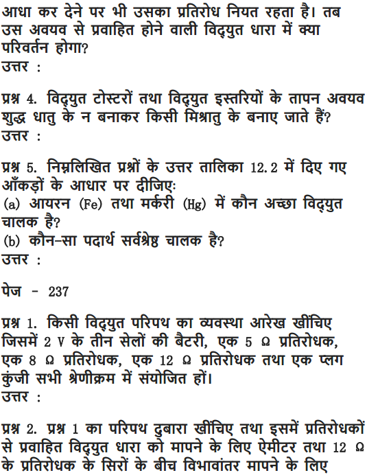
4. Why are coils of electric toasters and electric irons made of an alloy rather than a pure metal?
The resistivity of an alloy is higher than the pure metal. Moreover, at high temperatures, the alloys do not melt readily. Hence, the coils of heating appliances such as electric toasters and electric irons are made of an alloy rather than a pure metal.
5. Use the data in Table 12.2 to answer the following -
Table 12.2 Electrical resistivity of some substances at 20°C
− | Material | Resistivity (Ω m) |
| Conductors | Silver | 1.60 × 10⁻⁸ |
| Copper | 1.62 × 10⁻⁸ | |
| Aluminium | 2.63 × 10⁻⁸ | |
| Tungsten | 5.20 × 10⁻⁸ | |
| Nickel | 6.84 × 10⁻⁸ | |
| Iron | 10.0 × 10⁻⁸ | |
| Chromium | 12.9 × 10⁻⁸ | |
| Mercury | 94.0 × 10⁻⁸ | |
| Manganese | 1.84 × 10⁻⁶ | |
| Constantan (alloy of Cu and Ni) | 49 × 10−6 | |
| Alloys | Manganin (alloy of Cu, Mn and Ni) | 44 × 10−6 |
| Nichrome (alloy of Ni, Cr, Mn and Fe) | 100 × 10−6 | |
| Glass | 1010 − 1014 | |
| Insulators | Hard rubber | 1013 − 1016 |
| Ebonite | 1015 − 1017 | |
| Diamond | 1012 − 1013 | |
| Paper (dry) | 1012 |
i) Which among iron and mercury is a better conductor ?
Resistivity of iron = 10.0 x 10⁻⁸ Ω m
Resistivity of mercury = 94.0 x 10⁻⁸ Ω m.
Thus iron is a better conductor because it has lower resistivity than mercury.
(ii) Which material is the best conductor ?
It can be observed from Table 12.2 that the resistivity of silver is the lowest among the listed materials.Because silver has the lowest resistivity (= 1.60 x 10⁻⁸ Ω m), therefore silver is the best conductor.
Page No: 213
1. Draw a schematic diagram of a circuit consisting of a battery of three cells of 2 V each, a 5 Ω resistor, an 8 Ω resistor, and a 12 Ω resistor, and a plug key, all connected in series.
The required circuit diagram is shown below :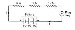
Three cells of potential 2 V, each connected in series therefore the potential difference of the battery will be 2 V + 2 V + 2 V = 6V. The following circuit diagram shows three resistors of resistances 5 Ω, 8 Ω and 12 Ω respectively connected in series and a battery of potential 6 V and a plug key which is closed means the current is flowing in the circuit.
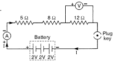
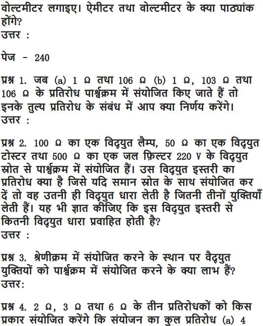
2. Redraw the circuit of question 1, putting in an ammeter to measure the current through the resistors and a voltmeter to measure potential difference across the 12 Ω resistor. What would be the readings in the ammeter and the voltmeter?
The required circuit diagram is shown on the right.
Total voltage, V = 3 x 2 = 6V
Total resistance, R = 5Ω + 8Ω + 12Ω = 25Ω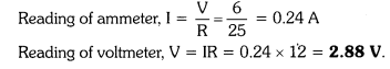
How?
=>An ammeter should be connected in the circuit in series with the resistors. To measure the potential difference across the resistor it should be connected in parallel, as shown in the following figure.

Ohm’s law can be used to obtain the readings of ammeter and voltmeter. According to Ohm’s law,
V = IR,
Where,
Potential difference, V = 6 V
Current flowing through the circuit/resistors = I
Resistance of the circuit, R = 5 + 8 + 12 = 25Ω
I = V/R = 6/25 = 0.24 A
Potential difference across 12 Ω resistor = V1
Current flowing through the 12 Ω resistor, I = 0.24 A
Therefore, using Ohm’s law, we obtain
V1 = IR = 0.24 x 12 = 2.88 V
Therefore, the reading of the ammeter will be 0.24 A.
The reading of the voltmeter will be 2.88 V.
Page No: 216
1. Judge the equivalent resistance when the following are connected in parallel − (a) 1 Ω and 106Ω, (b) 1 Ω and 103Ω and 106Ω.
a) When 1 Ω and 106 Ω are connected in parallel:
Let R be the equivalent resistance.

Therefore, equivalent resistance ≈ 1 Ω
(b) When 1Ω, 103 Ω and 106 Ω are connected in parallel:

Therefore, equivalent resistance = 0.999 Ω
2. An electric lamp of 100 Ω, a toaster of resistance 50 Ω, and a water filter of resistance 500 Ω are connected in parallel to a 220 V source. What is the resistance of an electric iron connected to the same source that takes as much current as all three appliances, and what is the current through it?
Resistance of electric lamp, R1 = 100 Ω
Resistance of toaster, R2 = 50 Ω
Resistance of water filter, R3 = 500 Ω
Equivalent resistance Rp of the three appliances connected in parallel, is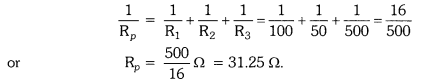
Resistance of electric iron = Equivalent resistance of the three appliances connected in parallel = 31.25 Ω
Applied voltage, V = 220 V
Current, I =
3. What are the advantages of connecting electrical devices in parallel with the battery instead of connecting them in series?
Ans:Advantages of connecting electrical devices in parallel with the battery are :
- In parallel circuits, if an electrical appliance stops working due to some defect, then all other appliances keep working normally.
- In parallel circuits, each electrical appliance has its own switch due to which it can be turned on turned off independently, without affecting other appliances.
- In parallel circuits, each electrical appliance gets the same voltage (220 V) as that of the power supply line.
- In the parallel connection of electrical appliances, the overall resistance of the household circuit is reduced due to which the current from the power supply is high
4. How can three resistors of resistances 2 Ω, 3 Ω and 6 Ω be connected to give a total resistance of (a) 4 Ω, (b) 1 Ω?
i) We can get a total resistance of 4Ω by connecting the 2Ω resistance in series with the parallel combination of 3Ω and 6Ω.![]()
(ii) We can obtain a total resistance of 1Ω by connecting resistors of 2 Ω, 3 Ω and 6 Ω in parallel.![]()
Or

Therefore, their equivalent resistance will be given by

Therefore, the equivalent resistance of the circuit = 2 Ω + 2 Ω = 4 Ω
Hence the total resistance of the circuit is 4 Ω.
(b) The following circuit diagram shows the connection of the three resistors.


5. What is (a) the highest, (b) the lowest total resistance that can be secured by combinations of four coils of resistance 4 Ω, 8 Ω, 12 Ω, 24 Ω?
There are four coils of resistances 4 Ω, 8 Ω, 12 Ω and 24 Ω respectively.
(a) If these coils are connected in series, then the equivalent resistance will be the highest, given by the sum 4 + 8 + 12 + 24 = 48 Ω
(b) If these coils are connected in parallel, then the equivalent resistance will be the lowest, given by

Therefore, 2 Ω is the lowest total resistance.
Page No: 218
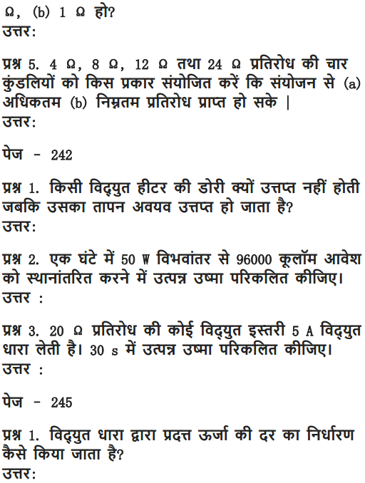
1. Why does the cord of an electric heater not glow while the heating element does?
Heat generated in a circuit is given by I2R t. The heating element of an electric heater made of nichrome glows because it becomes red-hot due to the large amount of heat produced on passing current because of its high resistance, but the cord of the electric heater made of copper does not glow because negligible heat is produced in it by passing current because of its extremely low resistance.
2. Compute the heat generated while transferring 96000 coulomb of charge in one hour through a potential difference of 50 V.
Given Charge, Q = 96000C
Time, t= 1hr = 60 x 60= 3600s
Potential difference, V= 50volts
Now we know that H= VIt
So we have to calculate I first
As I= Q/t
∴ I = 96000/3600 = 80/3 A

Therefore, the heat generated is 4.8 x 10⁶ J.
3. An electric iron of resistance 20 Ω takes a current of 5 A. Calculate the heat developed in 30 s
The amount of heat (H) produced is given by the joule's law of heating asH= Vlt
Where,
Current, I = 5 A
Time, t = 30 s
Voltage, V = Current x Resistance = 5 x 20 = 100 V
Therefore, the amount of heat developed in the electric iron is 1.5 x 10⁴ J.
Page No: 220
1. What determines the rate at which energy is delivered by a current?
The rate of consumption of electric energy in an electric appliance is called electric power. Hence, the rate at which energy is delivered by a current is the power of the appliance.
2. An electric motor takes 5 A from a 220 V line. Determine the power of the motor and the energy consumed in 2 h.
Power (P) is given by the expression,P = VI
Where,
Voltage,V = 220 V
Current, I = 5 A
P= 220 x 5 = 1100 W
Energy consumed by the motor = Pt
Where,
Time, t = 2 h = 2 x 60 x 60 = 7200 s
∴ P = 1100 x 7200 = 7.92 x 10⁶ J
Therefore, power of the motor = 1100 W
Energy consumed by the motor = 7.92 x 10⁶ J
Page No: 221
NCERT Solutions for Class 10 Science Chapter 12 Textbook Chapter End Questions
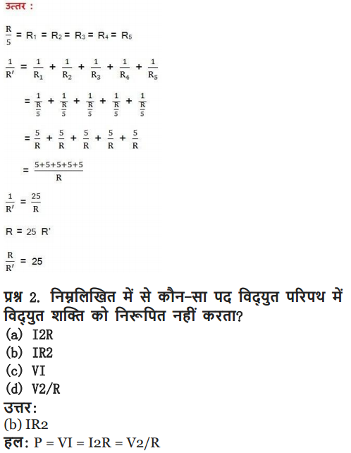
1. A piece of wire of resistance R is cut into five equal parts. These parts are then connected in parallel. If the equivalent resistance of this combination is R', then the ratio R/R' is -(a) 1/25
(b) 1/5
(c) 5
(d) 25
► (d) 25
2. Which of the following terms does not represent electrical power in a circuit?
(a) I2R
(b) IR2
(c) VI
(d) V2/R
► (b) IR2
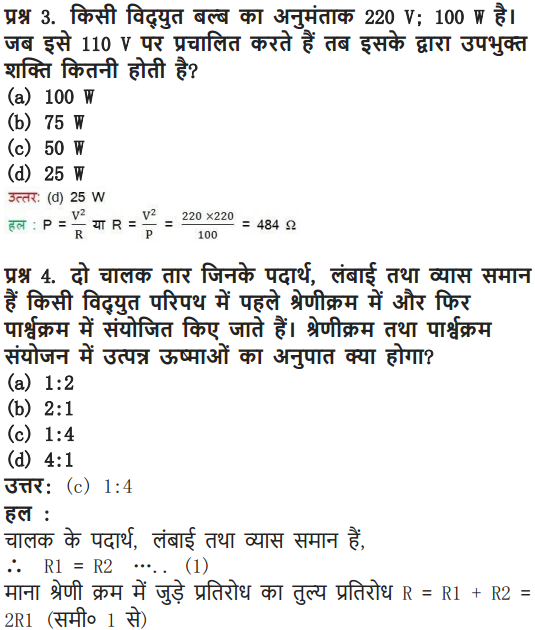
3. An electric bulb is rated 220 V and 100 W. When it is operated on 110 V, the power consumed will be -
(a) 100 W
(b) 75 W
(c) 50 W
(d) 25 W
► (d) 25 W
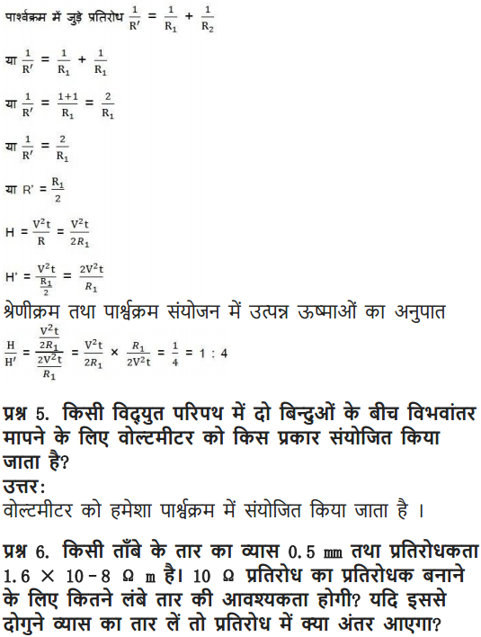
4. Two conducting wires of the same material and of equal lengths and equal diameters are first connected in series and then parallel in a circuit across the same potential difference. The ratio of heat produced in series and parallel combinations would be -
(a) 1:2
(b) 2:1
(c) 1:4
(d) 4:1
► (c) 1:4
5. How is a voltmeter connected in the circuit to measure the potential difference between two points
A voltmeter is connected in parallel to measure the potential difference between two points.
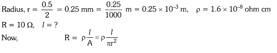
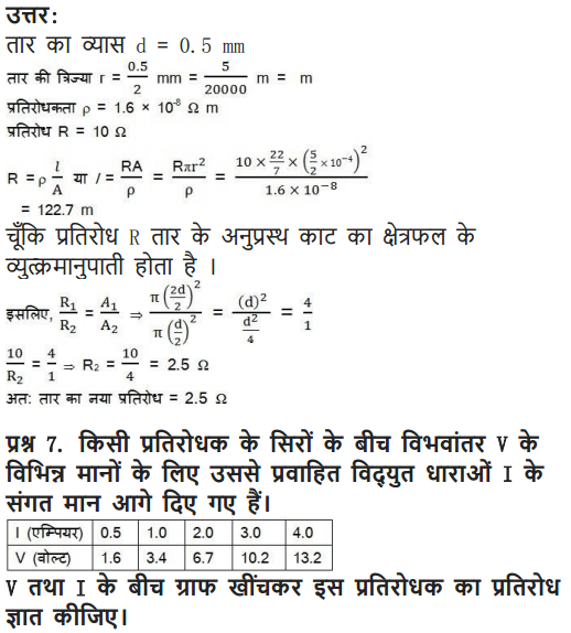
.6. A copper wire has diameter 0.5 mm and resistivity of 1.6 × 10⁻⁸ Ω m. What will be the length of this wire to make its resistance 10 Ω? How much does the resistance change if the diameter is doubled?
Area of cross-section of the wire, A =π (d/2) 2
Diameter= 0.5 mm = 0.0005 m
Resistance, R = 10 Ω
We know that

Therefore, the length of the wire is 122.7 m and the new resistance is 2.5 Ω.
Or
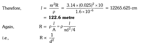
If a wire of diameter doubled to it is taken, then area of cross-section becomes four times.
New resistance =
Decrease in resistance = (10 – 2.5) Ω = 7.5 Ω
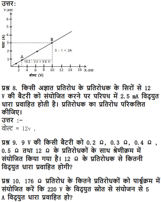
7. The values of current I flowing in a given resistor for the corresponding values of potential difference V across the resistor are given below −
I (amperes ) | 0.5 | 1.0 | 2.0 | 3.0 | 4.0 |
V (volts) | 1.6 | 3.4 | 6.7 | 10.2 | 13.2 |
Plot a graph between V and I and calculate the resistance of that resistor.
Answer
The plot between voltage and current is called IV characteristic. The voltage is plotted on x-axis and current is plotted on y-axis. The values of the current for different values of the voltage are shown in the given table.
V (volts) | 1.6 | 3.4 | 6.7 | 10.2 | 13.2 |
I (amperes ) | 0.5 | 1.0 | 2.0 | 3.0 | 4.0 |
The IV characteristic of the given resistor is plotted in the following figure.

The slope of the line gives the value of resistance (R) as,
Therefore, the resistance of the resistor is 3.4 Ω.
8. When a 12 V battery is connected across an unknown resistor, there is a current of 2.5 mA in the circuit. Find the value of the resistance of the resistor.
Resistance (R) of a resistor is given by Ohm's law as,V= IR
R= V/I
Where,
Potential difference, V= 12 V
Current in the circuit, I= 2.5 mA = 2.5 x 10⁻³ A

Therefore, the resistance of the resistor is 4.8 kΩ
9. A battery of 9 V is connected in series with resistors of 0.2 Ω, 0.3 Ω, 0.4 Ω, 0.5 Ω and 12 Ω, respectively. How much current would flow through the 12 Ω resistor?
Total resistance, R = 0.2 Ω + 0.3 Ω + 0.4 Ω + 0.5 Ω + 12 Ω – 13.4 Ω
Potential difference, V = 9 V
Current through the series circuit, I =
∵ There is no division of current in series. Therefore current through 12 Ω resistor = 0.67 A.
Or
There is no current division occurring in a series circuit. Current flow through the component is the same, given by Ohm’s law as
Where,
R= 0.2 + 0.3 + 0.4 + 0.5 + 12 = 13.4 Ω
I= 9/13.4 = 0.671 A
Therefore, the current that would flow through the 12 Ω resistor is 0.671 A.
10. How many 176 Ω resistors (in parallel) are required to carry 5 A on a 220 V line?
Suppose n resistors of 176 Ω are connected in parallel.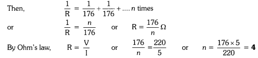
Thus 4 resistors are needed to be connect.
Or
For x number of resistors of resistance 176 Ω, the equivalent resistance of the resistors connected in parallel is given by Ohm's law asV= IR
R= V/I
Where,
Supply voltage, V= 220 V
Current, I = 5 A
Equivalent resistance of the combination = R,given as

Therefore, four resistors of 176 Ω are required to draw the given amount of current.
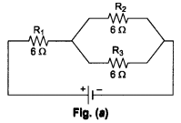
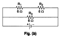
11. Show how you would connect three resistors, each of resistance 6 Ω, so that the combination has a resistance of (i) 9 Ω, (ii) 4 Ω.
(i) When we connect R1 in series with the parallel combination of R2 and R3 as shown in Fig. (a).
The equivalent resistance is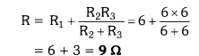
(ii) When we connect a series combination of R1 and R2 in parallel with R3, as shown in Fig. (b), the equivalent resistance is![]()
Or
If we connect the resistors in series, then the equivalent resistance will be the sum of the resistors, i.e., 6 Ω + 6 Ω + 6 Ω = 18 Ω, which is not desired. If we connect the resistors in parallel, then the equivalent resistance will be 6/2 = 3 Ω is also not desired. Hence, we should either connect the two resistors in series or parallel.
(a) Two resistor in parallel

Two 6 Ω resistors are connected in parallel. Their equivalent resistance will be

The third 6 Ω resistor is in series with 3 Ω. Hence, the equivalent resistance of the circuit is 6 Ω+ 3 Ω = 9 Ω.
(b) Two resistor in series

The third 6 Ω resistor is in parallel with 12 Ω. Hence, equivalent resistance will be

12. Several electric bulbs designed to be used on a 220 V electric supply line, are rated 10 W. How many lamps can be connected in parallel with each other across the two wires of 220 V line if the maximum allowable current is 5 A?
Here, current, I = 5 A, voltage, V = 220 V
∴ Maxium power, P = I x V = 5 x 220 = 1100W
Required no. of lamps
∴ 110 lamps can be connected in parallel.
Or
Resistance R1 of the bulb is given by the expression,
Supply voltage, V = 220 V
Maximum allowable current, I = 5 A
Rating of an electric bulb P=10watts
Because R=V2/P

∴ Number of electric bulbs connected in parallel are 110.
13. A hot plate of an electric oven connected to a 220 V line has two resistance coils A and B, each of 24 Ω resistances, which may be used separately, in series, or in parallel. What are the currents in the three cases?
(i) When the two coils A and B are used separately. R = 24 Ω, V = 220 V![]()
(ii) When the two coils are connected in series,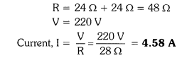
(iii) When the two coils are connected in parallel.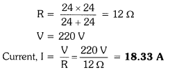
Or
Supply voltage, V= 220 V
Resistance of one coil, R= 24 Ω
According to Ohm's law,
V= I1R1
Where,
I1 = V/R1 = 220/24 = 9.166 A
Therefore, 9.16 A current will flow through the coil when used separately.
(ii) Coils are connected in series
According to Ohm's law,V = I2R2
Where,
I2 = V/R2 = 220/48 = 4.58 A
Therefore, 4.58 A current will flow through the circuit when the coils are connected in series.
(iii) Coils are connected in parallel

According to Ohm's law,
V= I3R3
Where,
I3 is the current flowing through the circuit I3 = V/R3 = 220/12 = 18.33 A
Therefore, 18.33 A current will flow through the circuit when coils are connected in parallel.
14. Compare the power used in the 2 Ω resistor in each of the following circuits: (i) a 6 V battery in series with 1 Ω and 2 Ω resistors, and (ii) a 4 V battery in parallel with 12 Ω and 2 Ω resistors.
(i) The circuit diagram is shown in figure.
Total resistance, R = 1Ω + 2Ω = 3Ω
Potential difference, V = 6 V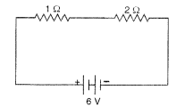
Power used in 2Ω resistor = I2R = (2)2 x 2 = 8 W
(ii) The circuit diagram for this case is shown :
Power used in 2 resistor = 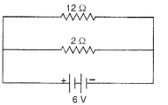
[ ∵ Current is different for different resistors in parallel combination.]
Or
1 Ω and 2 Ω resistors are connected in series. Therefore, equivalent resistance of the circuit, R = 1 + 2 = 3 Ω
According to Ohm’s law,
V = IR
Where,
I is the current through the circuit
I= 6/3 = 2 A
This current will flow through each component of the circuit because there is no division of current in series circuits. Hence, current flowing through the 2 Ω resistor is 2 A. Power is given by the expression,
P= (I)2R = (2)2 x 2 = 8 W
(ii) Potential difference, V = 4 V
12 Ω and 2 Ω resistors are connected in parallel. The voltage across each component of a parallel circuit remains the same. Hence, the voltage across 2 Ω resistor will be 4 V.
Power consumed by 2 Ω resistor is given by
P= V2/R = 42/2 = 8 W
Therefore, the power used by 2 Ω resistor is 8 W.
15. Two lamps, one rated 100 W at 220 V, and the other 60 W at 220 V, are connected in parallel to electric mains supply. What current is drawn from the line if the supply voltage is 220 V?
Both the bulbs are connected in parallel. Therefore, potential difference across each of them will be 220 V, because no division of voltage occurs in a parallel circuit.
Current drawn by the bulb of rating 100 W is given by,Power = Voltage x Current
Current = Power/Voltage = 60/220 A
Hence, current drawn from the line = 100/220 + 60/220 = 0.727 A
16. Which uses more energy, a 250 W TV set in 1 hr, or a 1200 W toaster in 10 minutes?
Energy used by 250 W TV set in 1 hour = 250 W x 1 h = 250 Wh
Energy used by 1200 W toaster in 10 minutes = 1200 W x 10 min
= 1200 x
Thus, the TV set uses more energy than the toaster.
17. An electric heater of resistance 8 Ω draws 15 A from the service mains 2 hours. Calculate the rate at which heat is developed in the heater
Here, R = 8 Ω, 1 = 15 A, t = 2 h
The rate at which heat is developed in the heater is equal to the power.
Therefore, P = I2 R = (15)2 x 8 = 1800 Js-1
Or
Rate of heat produced by a device is given by the expression for power as, P= I2R
Where,
Resistance of the electric heater, R= 8 Ω
Current drawn, I = 15 A
Therefore, heat is produced by the heater at the rate of 1800 J/s.
18. Explain the following.
(a) Why is the tungsten used almost exclusively for filament of electric lamps?
(b) Why are the conductors of electric heating devices, such as bread-toasters and electric irons, made of an alloy rather than a pure metal?
(c) Why is the series arrangement not used for domestic circuits?
(d) How does the resistance of a wire vary with its area of cross-section?
(e) Why are copper and aluminium wires usually employed for electricity transmission?
i) The tungsten is used almost exclusively for filament of electric lamps because it has a very high melting point (3300°C). On passing electricity through tungsten filament, its temperature reaches to 2700°C and it gives heat and light energy without being melted.
(ii) The conductors of electric heating devices such as bread-toasters and electric irons, are made of an alloy rather than a pure metal because the resistivity of an alloy is much higher than that of pure metal and an alloy does not undergo oxidation (or burn) easily even at high temperature.
(iii) The series arrangement is not used for domestic circuits because in series circuit, if one electrical appliance stops working due to some defect, than all other appliances also stop working because the whole circuit is broken.
(iv) The resistance of a wire is inversely proportional to its area of cross-section, i.e., Resistance R ∝ (1/πr2). If the area of cross section of a conductor of fixed length is increased, then resistance decreases because there are more free electrons for movement in conductor.
(v) Copper and aluminium wires usually employed for electricity transmission because they have very low resistances. So, they do not become too hot on passing electric current
Or
(a) The melting point and of Tungsten is an alloy which has very high melting point and very high resistivity so does not burn easily at a high temperature.
(b) The conductors of electric heating devices such as bread toasters and electric irons are made of alloy because resistivity of an alloy is more than that of metals which produces large amount of heat.
(c) In series circuits voltage is divided. Each component of a series circuit receives a small voltage so the amount of current decreases and the device becomes hot and does not work properly. Hence, series arrangement is not used in domestic circuits.
(d) Resistance (R) of a wire is inversely proportional to its area of cross-section (A), i.e. when area of cross section increases the resistance decreases or vice versa.
(e) Copper and aluminium are good conductors of electricity also they have low resistivity. So they are usually used for electricity transmission.
Class 10 Science Electricity Mind Map
Electricity
Study of Electric Charges at Rest and in Motion
Charge
Something associated with the matter due to which it produces and experiences electric and magnetic effects. Resides on the outer surface of the conductor.
Q = ne S.I. unit coulomb (C)
Electric Current (I)
The time rate of flow of charge (Q) through any cross-section
I =
Types of Current
Direct Current
Current whose magnitude and direction does not vary with time.
Alternating Current
Current whose magnitude and direction periodically changes with time.
Electric Potential
Work done per unit charge
V =
S.I. unit volt
Ohm’s law: If the physical conditions remain same, current I ∝ V => V = IR
R-electric resistance Substances which obey ohm’s law called ohmic and that do not obey called non-ohmic substances.
Dependence of Resistance
On length (l) and area of cross-section (A)
R ∝ l
∝
R =
ρ = resistivity
Resistivity depends on the material of the conductor only.
On Temperature
Rt = R0( 1 + αt)
α = temperature coefficient of resistance
Resistance (R): Obstruction offered to flow of electrons.
SI unit ohm
Resistance, R ∝
l = length and
m = mass of conducting wire
After stretching, if length increases by n times then resistance will increase by n2 times i.e., R2 = n2 R1. Similarly
if radius be reduced to
After stretching, if length of a conductor increases by x%, then resistance will increase by 2x% (valid only if x< 10%).
- Using n conductors of equal resistance, the number of possible combinations is 2n-1 .
- If the resistances of n conductors are totally different, then the number of possible combinations will be 2n .
- If n identical resistances are first connected in series and then in parallel, the ratio of the equivalent resistance is given by
RsRp=n21 - If a wire of resistance R is cut in n equal parts and then these parts are collected to form a bundle, then equivalent resistance of combination will be
Rn2 - If equivalent resistance of R1 and R2 in series and parallel be Rs and Rp respectively, then
R1 =12[Rs+R2s−4RsRp−−−−−−−−−−√]
and R2 ==12[Rs−R2s−4RsRp−−−−−−−−−−√]
Grouping of Resistances
Series Grouping of Resistances
Equivalent resistance, resistance, Rs = R1 + R2 + … + Rn
In this case same current flows through each resistance but potential difference in the ratio of resistance
Parallel Grouping of Resistances
In this case same potential across each resistance but current distributes in the reverse ratio of their resistances
Electric Circuit
The arrangement of various electrical components along which electric current flow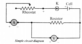
Heating Effect of Electric Current
As current flows through a conductor, the free electrons lose energy which is converted into heat.
Joule’s heating law
H ∝ I2
H ∝ R
H ∝ t
H = I2Rt = VIt
Practical Applications
- Electric heater, electric iron and water heater, etc. work on the principle of heating effect of current
- Electric bulb glows when electric current flows through the filament of the bulb
Electric Power
Rate at which electric energy is dissipated or consumed in a circuit,
P = VI ,
or P = I2R =
Watt is a smaller unit of power, its other bigger units are kilowatt (KW),
Megawatt (MW) and Horsepower (HP)
1 KW = 103W 1 MW = 106W
1 hp =746 W
The commercial unit of electrical energy is 1 Kwh.
1 Kwh = 3.6 × 10⁶J
Elements of Circuit
Cell
Direct current source of electromotive force. Combination of two or more cells is called battery.![]()
Rheostat
Wire of special type of alloy like manganin, Eureka, nichrome, etc. is wound on a hollow cylinder of china clay. It controls the current in the electric circuit.![]()
Switch
It is used to close or open the electric circuit, controls the movement of electrons in a circuit.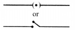
Voltmeter
Measures the potential difference between two points in the circuit. Its resistance is high and it is used in parallel with the resistance wire.![]()
Fuse
It is a safety device having very thin wire which is made up of either tin or alloy of tin and lead.
This wire has low melting point so it melts and breaks the circuit easily if the current in the circuit exceeds.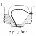
Ammeter
Measures the value of current flowing in the circuit.
The resistance of ammeter is small and it is used in series with the circuit.![]()
LED
It is a device which glows even if a weak electric current is allowed to flow through it
Now that you are provided all the necessary information regarding Electricity class 10 NCERT solutions and we hope this detailed article on NCERT Solutions For Class 10 Science Chapter 12 Electricity is helpful. If you have any doubt regarding this article or NCERT Solutions For Class 10 Science Chapter 12 Electricity, leave your comments in the comment section below and we will get back to you as soon as possible.
NCERT Solutions for Class 10 Science Chapter 12 Electricity (Hindi Medium)

Class 10 Science Electricity
NCERT Solutions for Class 10 Science Chapter 12 Electricity


